Rotation Clockworks
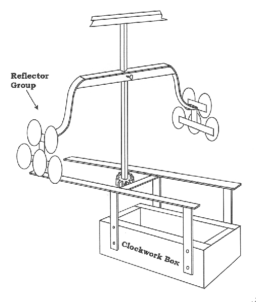
(Drawing by Author from Patent drawing)
Revolving Lamp Chandelier, Small Model, with two groups of five reflectors, typical of those used in the 1830s.
From Patent 1085, February 20, 1839. There also was a Large Model chandelier with two groups of seven reflectors.
The first rotation clockworks were developed to rotate chandeliers that supported the reflectors used for illumination in early lighthouses. In America, starting in 1812, Winslow Lewis contracted with Simon Willard, a famous Boston clock maker, to build all of the rotation machinery he used for his rotating lights. Simon Willard built a total of about 40 clockworks for Winslow Lewis’ revolving lights. He continued to make the clockworks until 1839 when he retired. In the period from 1839 through 1850, Benjamin F. Willard, Simon’s son, continued to provide and repair the clockworks. The early clockwork was described as follows: “The lighting apparatus consists of ten lamps, with the same number of parabolic reflectors and plano-convex lenses, supported upon two copper tables, which have the machinery for producing their revolutions attached. The lamps are divided into two clusters, and are so arranged upon the tables that each cluster of five lamps will display its light for a certain period during each revolution.”
“The motive power of the machinery is a weight of 228 pounds, attached to a rope, which is wound over a horizontal barrel; this barrel is connected with a spindle by means of a wheel and pinion, and upon the spindle the tables are placed: motion is in this manner communicated to the tables, and it is regulated by the revolution of a series of vanes, which are connected with the spindle by means of horizontal wheels and pinions.
Fresnel’s Lens Rotation Clockwork
From 1819 to 1825, Augustin Fresnel, who was then engineer to the French Lighthouse Service, studied the application of clockwork movements for the rotation of the optics in lighthouses. The rotation of the optics had to be very precise to assure that the mariner would see the same timing between each flash of the rotating lens; the use of a clockwork driven by a weight seemed indicated. Most of the clockwork movements at that time were based on the escapement principal. For a period of two years, the rotation of the optics in Fresnel’s first rotating lens, installed in the lighthouse at Cordouan, was produced by a clockwork escapement device designed and manufactured by Monsieur Bernard Wagner. The considerable inertia of this heavy flashing lens caused jerky movements of both the lens and clockwork. Fresnel concluded that it was an “unceasing cause of deterioration”, especially for optical devices made from glass, which were much heavier than the reflectors used at Cordouan during the previous thirty years.
Fresnel wanted to use a device with continuous rotation, without an escapement system, and began a search for a new clockwork design.
According to the writings of Augustin Henry’s sons, Fresnel and Augustin Henry met during the opening of the new breakwater constructed in the harbor of Dunkerque in 1824, where Henry had just installed a new bell tower. Fresnel explained the problems with the escapement clock drive to Augustin Henry. Within a few months Monsieur Henry created a new clock mechanism that, while preserving the main workings of his clocks, was supplied with a regulator based on centrifugal force. This was the kind used by James Watt for steam engines; it allowed the clock to maintain a continuous rotation with sufficiently regular speed for the needs of the lighthouses.
Early in 1825, Augustin Henry (later known as Henry-Lepaute) executed his first clockwork equipped with the new regulator design that he called the ‘flying pendulum.’ Augustin Fresnel wrote about the new regulator, stating: “The testing of the first machine with a flying pendulum was done in front of the Commission of the Lighthouses on March 25 1825; but the inventor of the new regulator was not sure enough to make it the final application.” It took several months of testing before Augustin Henry would commit to the use of the ‘flying pendulum’, but ultimately he introduced it into all the clockworks he produced for lens rotation within lighthouses. The Wagner escapement clockwork at Cordouan was replaced in 1825 with the new Augustin Henry clockwork design.
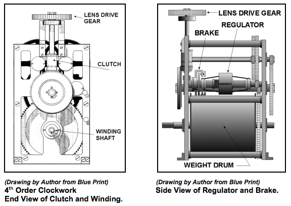
A rotation clockwork consists of the clock driven by a weight and cable on a drive drum, a speed regulator that maintains a constant turning speed, and a drive shaft and gear that drives the lens.
Major Styles of Rotation Clockworks
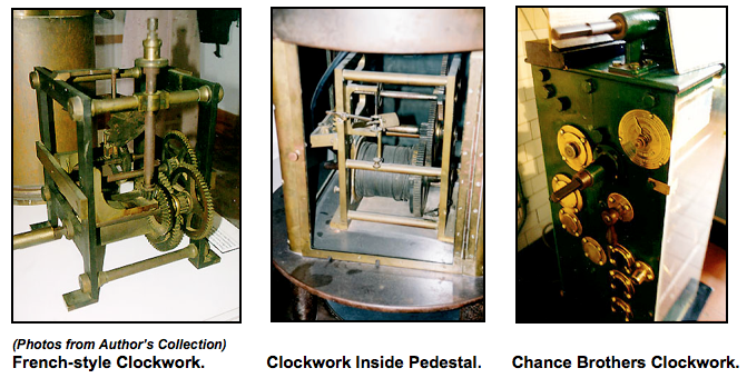
American Style 4th Order Clockwork
Rotation Clockworks Were Made of Several Major Assemblies
- The clockwork drive weight
- Various weight attachment designs
- The maintenance gearing
- The winding handle and gearing
- Various speed regulator designs
- The lens drive gearing
Clockwork Drive Weights
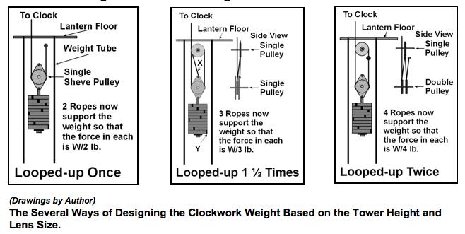
The clockwork was driven by a heavy weight that was attached to a cable wound around a drum in the clockwork mechanism. Some weights traveled up and down in a special channel built into the wall of the lighthouse tower and used pulleys to guide the wire cable from the clockwork drum to the weight. Other weights ascended and descended inside a tube formed by the central pole of the spiral stairs; still others traveled up and down in the open in the center of the tower, or sometimes, guided by cables extending down the center of the tower.
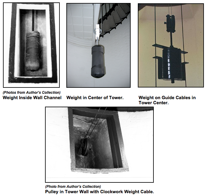
Clockwork Weight Attachment Designs
There was a problem associated with the weights in that the weight cable would wear out over a long period of time. If the cable should break, the massive weight could plummet to the base of the tower. In many tower designs this was only a minor problem because the weight was enclosed in a chamber within the wall of the tower or within the central spiral staircase support tube. However, in some tower designs the weight hung in the open in the center of the tower. In these designs, when the cable broke, the weight would come crashing down and could seriously damage the base of the tower or potentially kill anyone standing under it. To elevate this potential danger, a special circular railing was placed in the center of the base of the tower that enclosed a sand pit several feet in depth. If the weight fell it would land in the sand pit without significant damage while the railing prevented persons from standing where the weight might fall.
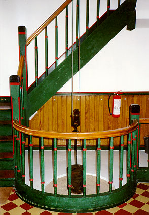
(Photo courtesy Egbert Koch Collection) Sand Pit at Base of Tower.
Maintenance Gearing
When the driving weight is being rewound, that is, bringing it to the top of the tower, the optic must continue to revolve in the same direction and at the same speed. In order to accomplish this, a complex set of epi-cyclic gears were fitted ‘between’ the weight-cable drum and the ‘A’ wheel drive gear, their function being to keep the driving force on the ‘A’ wheel gear constant and in one direction only.
The drawing below shows the type of Maintenance Gear used by Chance Brothers.
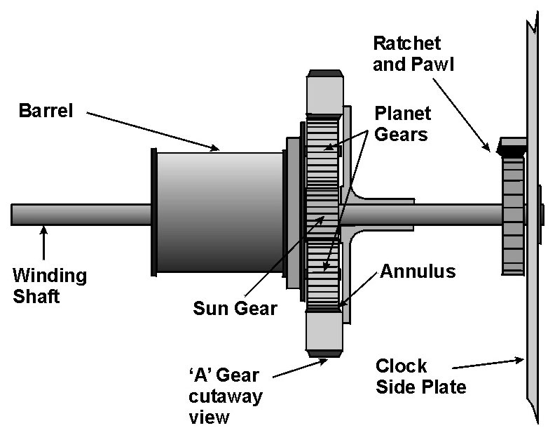
(Drawing by Author from a sketch by F. W. Cooper) Chance Brothers Maintenance Gearing.
General operation - The barrel runs free on the winding shaft, but it also carries the two planet gear shafts and the planet gears. The sun gear and ratchet wheel are fixed to the winding shaft. The ‘A’ wheel moves freely on the winding shaft. The pawl is pivoted on a stud attached to the clock frame and the pawl engages the ratchet wheel under spring pressure, so that the winding shaft with the sun gear will be held stationary except during wind-up. The pawl is spring loaded and the spring pressure can be overcome easily when the pawl is raised by the cam action of the ratchet wheel teeth when the winding shaft is turned during wind-up. However, the pawl and ratchet also perform an anti back-up function during windup.
While driving – Since the ratchet wheel is fastened to the winding shaft and the pawl is attached to the clock frame, the winding shaft is held steady in the drive direction. The barrel and the ‘A’ wheel will turn on the winding shaft being pulled in the direction that the weight cable is wound on the barrel and powered by the weight because the planet gears are rotating on their shafts, which are fixed to the barrel. They are engaged in the teeth of the sun gear and annulus gear teeth inside the ‘A’ wheel and allow the ‘A’ wheel to move with the barrel.
While winding up – Remember the shafts for the planet wheels are attached to the barrel. When the winding shaft is turned the sun gear turns and the planet gears begin turning in the direction of the pull of the weight cable and operate as wheels within wheels allowing the barrel to move in the opposite direction from the ‘A’ wheel as the pawl cams over the ratchet wheel teeth in this direction. The ‘A’ wheel is prevented from turning in the reverse direction, now being taken by the barrel, by the weight and cable.
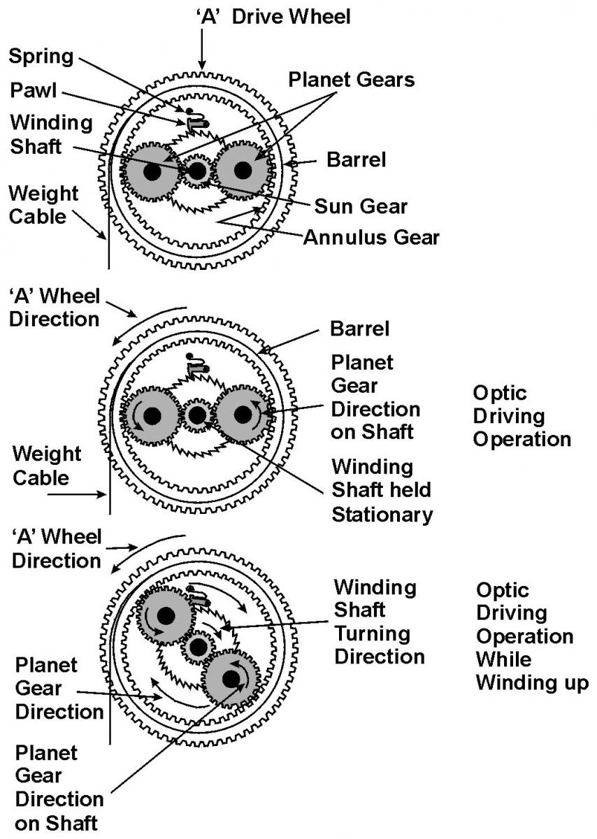
(Drawing by Author) Maintenance Gear Operation – Chance Brothers Style.
The Winding Handle and Gearing
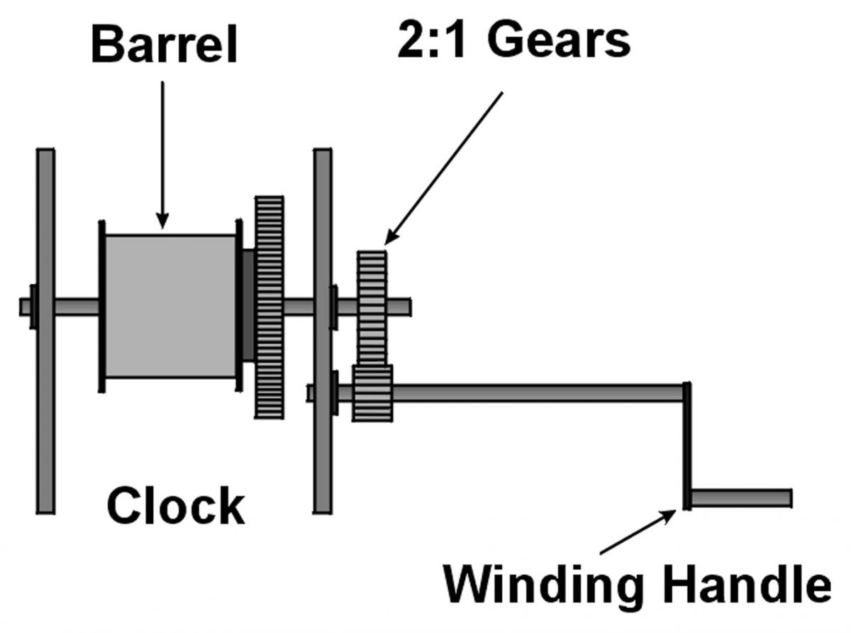
(Drawing by Author from a sketch by F. W. Cooper) The Clockwork Winding Handle.
The winding handle is mounted external to the clock frame and drives the winding shaft and barrel through a 2:1 gear ratio. This makes winding considerably easier for the keeper. The weight had to be wound, twice each night, which would keep the lens operating for about eight hours on one winding. In some early designs the clock had to be rewound as often as every two to four hours during the night.
Speed Regulator Designs
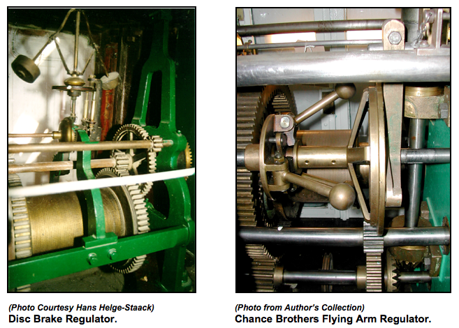
The clock regulator was designed to maintain a constant speed of lens rotation. Over the years, many types of clock regulators were tried. The first type of regulator was operated by centrifugal force and controlled a set of fan blades that changed angle as the speed increased causing air drag to slow the clockwork and ultimately the lens speed. Other designs used a disc brake in combination with a fan blade or just a disc brake to control the speed. All of the designs used centrifugal force to actuate the speed regulator.
Types of Speed Regulators
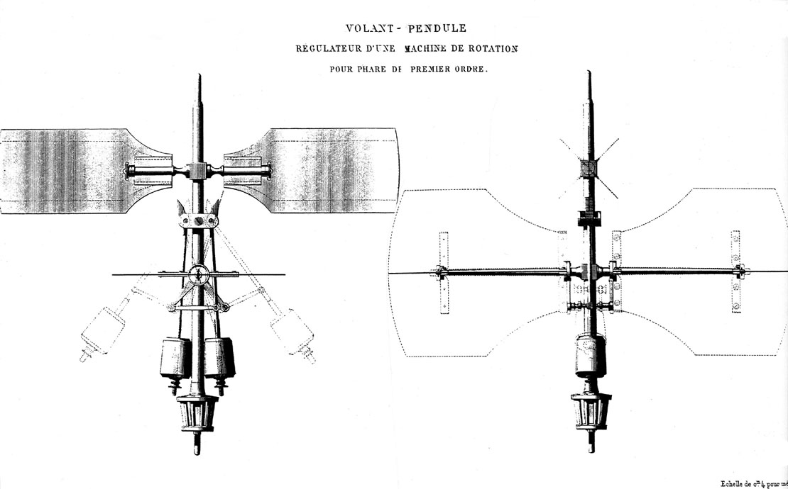
(Drawing from “Oeuvres Completes de Fresnel”) Flying Pendulum Design of Augustin Henry-Lepaute.
Many other styles of clock speed regulators were tried.
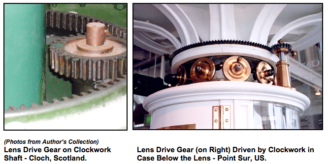
Lens Drive Gearing
The clockwork mechanism turned a final drive shaft that was oriented vertically, and had at its end a gear that was meshed with the gear on the bottom lens ring. Some lens rings used an internal gear while others used an external gear, as shown below.
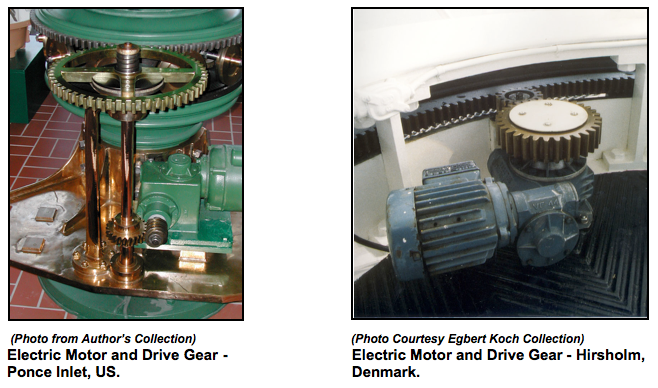
Modern Lens Drive Designs
Today’s lens drives use electric motors with reduction gearing to directly drive the lens.