The original Winslow Lewis Chandelier design
In 1810, Winslow Lewis, a sea captain who confessed that he knew nothing about lighthouse optics, patented what he called a “magnifying and reflecting lantern” for lighthouse work. His design included a lamp, a reflector, and a magnifier.
Winslow was variously characterized by his associates. Some said he provided extraordinary services to his country through his inventions, lighthouse construction and through his efforts in the maintenance of the lighthouses. Others called him an incompetent scoundrel who appropriated many of his inventions from others, produced shoddy construction of lighthouses and minimized any effort or expenditure related to lighthouse maintenance and improvements.
The Winslow Lewis design was crude, but he succeeded in impressing the government through actual trials of the design’s performance and low oil consumption, which were held at the Boston lighthouse. In 1812, U.S. Government paid Lewis over $ 20,000 for his invention.
The reflector was circular in construction and made of a thin sheet of copper formed in a generally spherical shape. It was plated with a slight film of silver with the grain and luster of tin wear, and when a finger was held near the reflector no distinct image of the finger was formed on the silvered surface. The early reflectors varied in size from 9 to 14 inches in diameter. The larger reflectors were so flimsy that when they were mounted on their wrought iron frame on the chandelier they were sometimes compressed significantly, altering their form and making their reflection capabilities still worse. In early models, the reflector was attached to the front of the oil reservoir and in most cases was set too far from the flame and therefore the flame was not in the focus of the reflector. A spherical reflector returns the rays of light back upon the flame and it is normal for 50% of the reflected light to be lost in passing through the flame. By accident, the Winslow Lewis design had the flame too far forward of the reflector focus, which actually helped to allow more of the reflected light to be used.
The magnifier was made of a cast and polished, plano-convex, semi-transparent glass mass, 9 inches in diameter. Early models were 4 inches in thickness while later models were 2 ½ inches; all were made of bottle-green glass. The glass was of such poor quality and the basic design placed the lamp so far out of the focus of the lens, that the lens was nearly useless. It was said that, “It made a bad light worse.” The distance from the back edge of the lens to the center of the flame varied considerably, from about 9 inches to as little as 5 ¼ inches. The magnifying lens was only used in association with the nine-inch reflector and was abandoned starting in 1828. Most were gone by 1838, and the last magnifier was removed from the Faulkner’s Island Lighthouse in 1840.
The lamp in Lewis’ design was a crudely built Argand style lamp with a three-quarter inch burner. The original lamp also used a short glass chimney and a simple woven-cotton lamp wick, which was poorly made, and resulted in inefficient fuel usage.
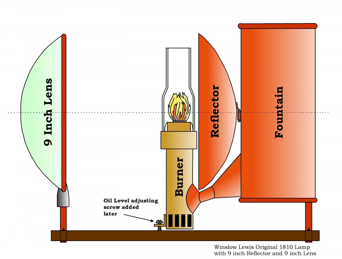
It was thought that all copies of the drawings for the Winslow Lewis patent were destroyed, and that no physical examples existed of any part of the Winslow Lewis illumination equipment. A few written descriptions exist, some of which have been used above, but these descriptions had previously only been converted into very crude drawings of just some parts of the Winslow Lewis design. Fortunately, a copy of the patent drawings has been located, and an actual 9-inch lens has been found. In addition, several more detailed drawings of the Winslow Lewis design have been created from the written descriptions along with various patent drawings and through observation and photographs of the 9-inch lens.
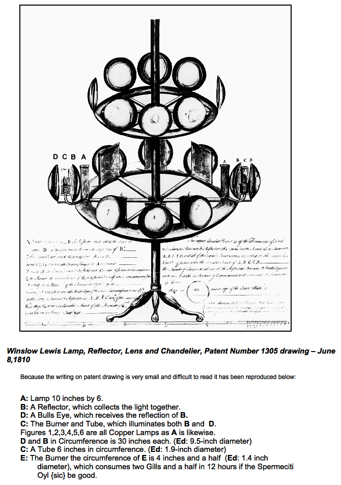
Figures 7,8,9,10,11 and 12 are all Bulls Eyes of the same circumference as D’s, with Lamps, Burners and Reflectors as A, B, and C are and of the same size. What they rest on is a Circular Frame of the diameter of 4 foot supported on a stand 3 foot high.
The upper Circular Stand is of the diameter of 3 feet with Lamps, Burners and Reflectors the same as the stand, which supports A, B, C and D, and all of the same dimensions supported on the same stand 2 foot and 2 inches above the Circular Stand of A, B, C and D.
The Number of Lamps in all are 16, the Reflectors, Burners and Bulls Eyes are each 16, and the 16 Burners by experiment will consume 5 quarts in 12 hours.
The exact size of the Cotton Wick was ¾ inch diameter.
When illuminated one of these Bulls Eyes may be seen at any point of the compass for before you loose the sight of one another presents itself in view
The original description and drawings of the Winslow Lewis patent were destroyed in a fire at the Patent Bureau on December 15, 1836, and it was reported that 5th Auditor, Stephen Pleasonton, did not keep a copy of the patent drawing. However, the drawing shown above was found in the collection of the Smithsonian Institution, its original source is unknown, but was probably from one of the copies often furnished by the Patent Bureau for examination or litigation. The drawing was made on paper that was dated to 1796, and there are good indications that it is a copy of the actual patent drawing for Patent 1305.
Winslow Lewis Lamp, 9 inch Reflector and 9 inch Lens, circa. 1810-1818.
The original patent drawing varied somewhat from the actual design that was produced. In the production design, shown above, the magnifying lens is held by a copper ring and is attached to a hard copper 3/8-inch square shaft. This shaft fit into a square hole in the chandelier and was held in proper vertical height by a metal pin that fit through the shaft. The lamp was mounted in the same fashion, and its oil level was adjusted by tipping the lamp forward and backward. This tipping was accomplished by placing wooden shims under the lamp burner and later by the addition of an oil level adjusting screw.
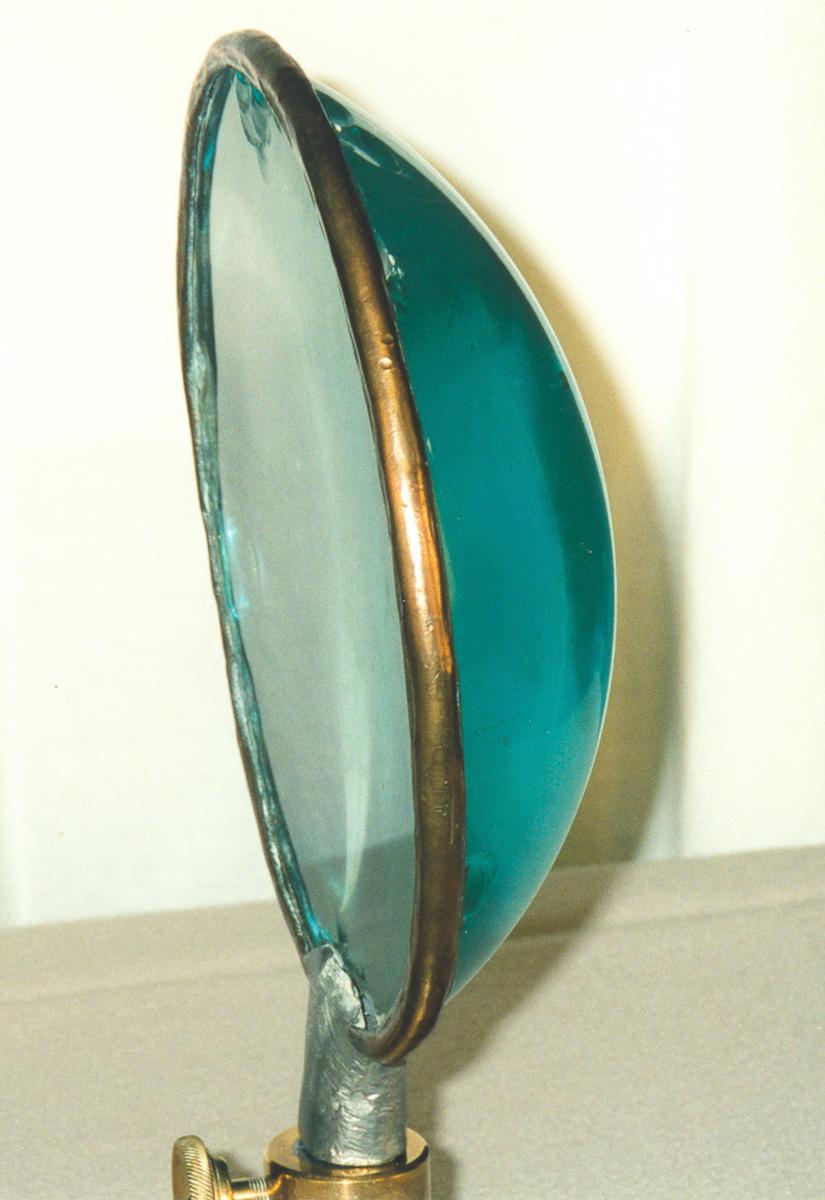
An original Winslow Lewis 9-inch lens made ca. 1818.
The lamps with larger reflectors were mounted differently and had oil level adjusting screws on the chandelier in a mounting plate behind the lamp fountain, as shown below.

(Drawing by Author from Patent 3692, and descriptions in 25th Congress, 3rd Session, Doc. 24, pp. 46 and 27th Congress, 3rd Session, Doc. 183, pp. 52,55
Note: this drawing is based mostly on verbal descriptions and may not reflect the exact design.)
Winslow Lewis – Benjamin Hemmenway Lamp and Reflector in Chandelier mounting, ca. 1834-1844.
Winslow Lewis Lamp Chandeliers for Larger Reflectors
The Lantern Rooms were so small that the keepers had great difficulty walking between the chandelier and the outside windows. The fixed and revolving chandeliers were both capable of being rotated, to allow the keeper to stand in the doorway of the Lantern Room and turn the chandelier to bring each lamp to him for filling and cleaning. The keeper often failed to return the fixed chandelier to its correct position and sometimes one or more reflectors were left facing the land or the Lantern Room door.
Clockworks for rotation of the Lamp Chandelier
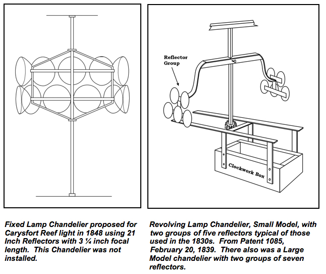
Winslow Lewis contracted with Simon Willard, a famous Boston clock maker, to build all of the rotation machinery he used for his rotating lights. Simon Willard built a total of about 40 clockworks for Winslow Lewis’ revolving lights. He continued to make the clockworks until 1839 when he retired. In the period from 1839 through 1850, Benjamin F. Willard, Simon’s son, continued to provide and repair the clockworks. The early clockwork was described as follows: “The lighting apparatus consists of ten lamps, with the same number of parabolic reflectors and plano-convex lenses, supported upon two copper tables, which have the machinery for producing their revolutions attached. The lamps are divided into two clusters, and are so arranged upon the tables that each cluster of five lamps will display its light for a certain period during each revolution.”
“The motive power of the machinery is a weight of 228 pounds, attached to a rope, which is wound over a horizontal barrel; this barrel is connected with a spindle by means of a wheel and pinion, and upon the spindle the tables are placed: motion is in this manner communicated to the tables, and it is regulated by the revolution of a series of vanes, which are connected with the spindle by means of horizontal wheels and pinions.
The clockwork itself was a high quality design made by an expert clockmaker. However, in typical Winslow Lewis fashion, the chandelier frame and pivot shaft with its bearings and drive gears were of poor quality, as attested to in the following description:
W. J. Grayson the Superintendent of Lights for the Charleston District, reported in 1843 on the new chandelier rotation mechanism installed at the Charleston light as follows. “The new clock, furnished by Mr. Lewis, has not performed well. The frame containing the lamps rests and revolves on a spindle, resting on a metal plate; and it wears so rapidly, as to embarrass the movement of the light. I will endeavor to attach so much of the old clock to the new, as to remedy the defect.”
Attachment of the Reflectors to the Chandelier
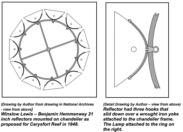
In the original Winslow Lewis design, the reflectors had a hook soldered to the back that slid down into a bracket attached to the front of the fountain of the lamp. The lamp also had two metal shafts projecting downward that fit into two holes in the circular chandelier tables.
By the 1840s, chandelier designs were more complex. Stephen Pleasonton stated that; “the lamps and reflectors are attached to the chandeliers by rings and solid yokes, made to the proper dimensions for perfect adjustment with screws, &c., and provided with catches or slots to prevent the keeper from losing the adjustment.”
Other Styles of Reflector Chandeliers
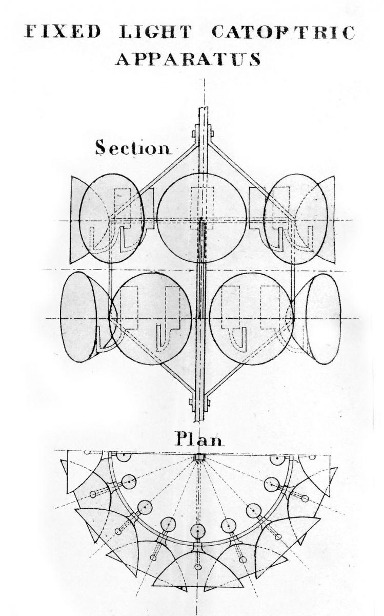
Fixed Chandelier.
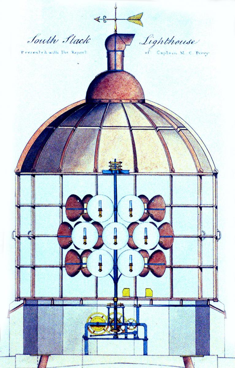
Revolving Chandelier.
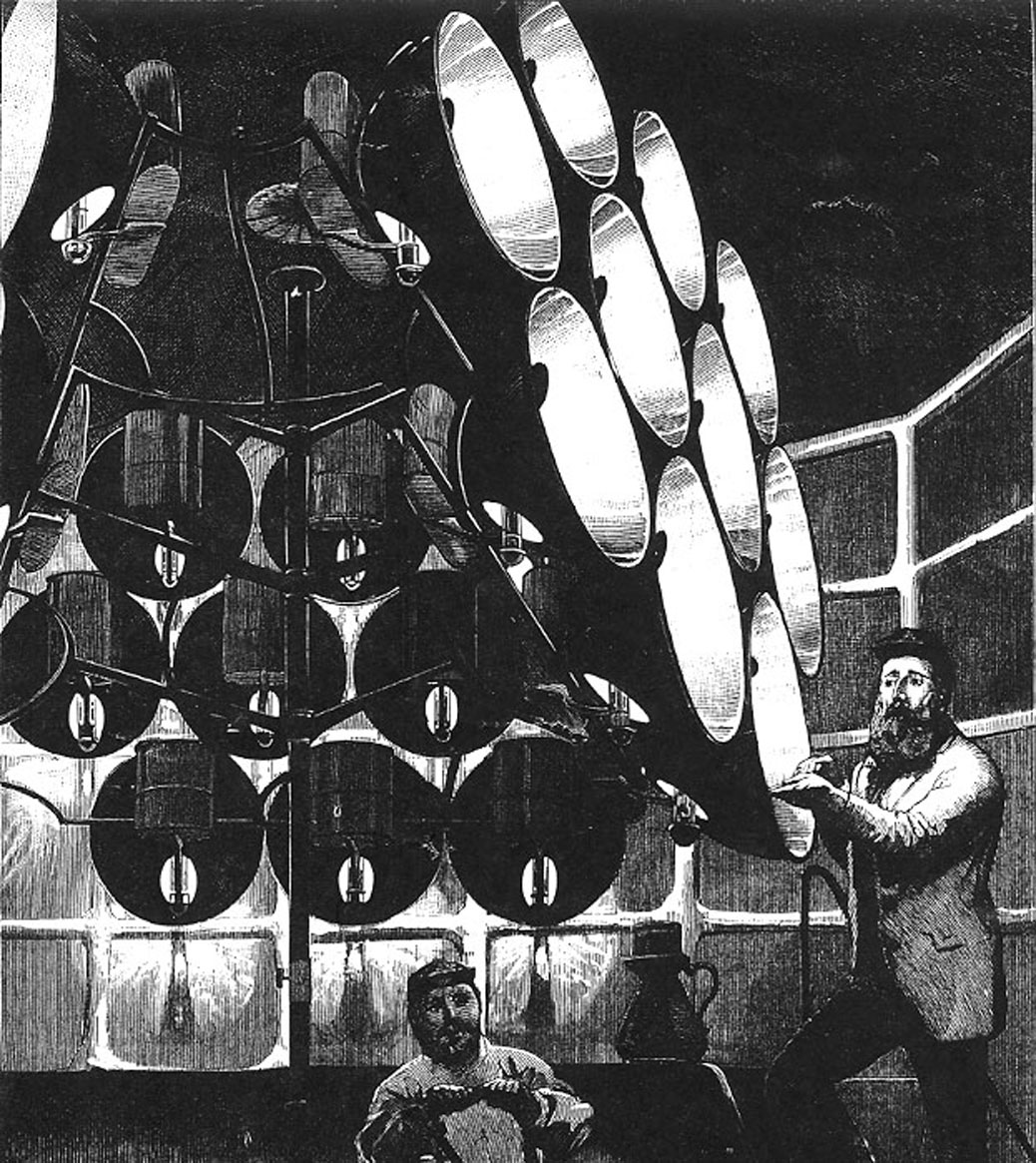
Revolving Chandelier with large number of Reflectors on three sides.