This is a story about the Catoptric system of lighthouse illumination. What is Catoptric? It's from the Greek word (Catoptron) for mirror, or reflection, and the lighthouse illumination system based on the principle of reflection was given the name Catoptric System in English.
The major problem with early lighthouses was the small output of light from the wood or coal fires then being used. Lighthouse designers were constantly looking for ways to produce more light. Experiments were made with the types of fuel being burned, with the design of the braziers, which held the burning fuel, and with ways to direct or concentrate the light from the fire. The first method of projecting and directing the light started with the design of the reflector. In this story we will discuss the various types of reflectors that were used to create the ‘Mirror of Light’.
Reflector Designs
Reflection occurs when a ray of light hits a painted or polished surface and is reflected from the surface. Highly polished metal surfaces behave as mirrors, and when they are made in the shape of a parabola they concentrate the light from a light source placed in the focus of the parabola.
Basic Reflector Types.
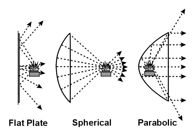
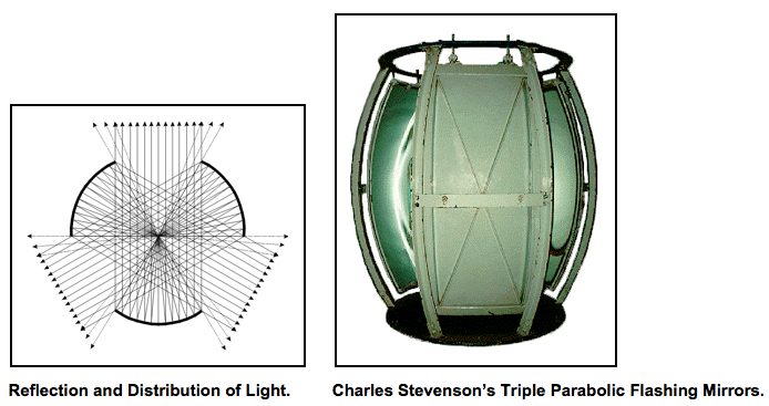
There are three basic types of reflecting surfaces, Flat, Spherical and Parabolic as shown in the drawing. Flat plate reflectors are seldom truly flat, nor are they always highly reflective. A flat plate reflector reflects light in many directions and only a small portion of the light is reflected forward in a direction useful to a mariner.
Spherical reflectors return the light rays to the focus of the reflector where the lamp is placed. A spherical reflector will appear to intensify the brightness of the flame, but will not form the light into a concentrated beam useful to the mariner.
Parabolic reflectors gather the light from the focus of the reflector and return it in a concentrated beam in the direction the reflector is facing. This concentrated beam of light can be directed to the horizon and can be manipulated to provide a very useful light for the mariner. However, approximately 30 percent of the total available light escapes from around the edge of the reflector and is not concentrated into the beam.
Problems with the manufacture of reflectors kept them from reaching their theoretical capabilities. The parabolic shape was very difficult to fashion by hand. Two general methods of construction were employed. In the early method, a sheet of metal, usually copper, was fashioned into a crude parabolic shape by hammering a flat sheet using only the skill of the craftsman as a guide. Later, wooden molds were carved by hand and checked against paper or brass templates. The sheets of metal were then formed into parabolic shapes by hammering into the mold, and still later, iron molds were used to create more refined parabolic reflectors. The copper reflectors were then polished to form a shinny surface to reflect the light. However, plain copper was not a very reflective surface and was soon abandoned. A second construction method used heavy silver cladding, which was bonded to the copper to improve its reflective qualities. Unfortunately silver oxidizes (tarnishes) rapidly leading to the need for continual polishing. The removal of the tarnish and also of the soot left on the reflector from the lamp flame, when chimney-less lamps were used, caused the need for polishing the reflectors on a very frequent basis. In many cases the silver cladding was polished so much that it was removed from the copper surface altogether, returning the reflector to a poor state of light reflection.
With any metallic surface, a portion of the light is absorbed into the surface by slight imperfections, scratches, soot, and the metal itself. It was found through experiment that the highest quality metal reflectors with the best silvering and polished surfaces still reflected just 55 percent of the available light. In addition, some of the light is lost around the edge of the reflector and it was determined that only 70 percent of the total light from the lamp was actually collected by the reflector. Thus the total light collected and sent in a useful direction by a nearly perfect reflector is a combination of the two factors just mentioned or about 39 percent, while an average quality reflector produced as little as 20 percent.
An Argand Lamp produced between 6 and 7 candlepower at any single point of observation. A high quality 21-inch diameter-silvered-parabolic reflector collected and reflected 39 percent of the total available light from the lamp creating a concentrated beam of light that increased the power of the lamp by about 350 times, and thus the combination Argand lamp and reflector produced 2450 candlepower.
The most powerful light from a parabolic reflector is concentrated in the central axis of its beam. At positions as little as 8 degrees on either side of the central axis the effective candlepower is only 10 percent of that in the center, and in areas beyond 8 degrees the light drops very quickly. This narrow divergence of the light beam required the mariner to be almost directly in line with the front of the reflector in order to see the light beam at a distance. The divergence is a function of the size of the lamp flame and the focal distance of the reflector, with the average reflector’s useful beam covering about 14 degrees of the horizon, and intense light covering about 5 degrees.
A Note About Candlepower
The determination of the light output of reflectors and lamps is usually measured in candlepower. In the early years of reflector development there were no accurate methods of measuring candlepower and later, in the early 1800s the methods used were very subjective and unscientific by our current standards. The candlepower is also dramatically affected by the size of the reflector, the type of oil used as a fuel, the maintenance of the lamp and polish of the reflector and by other factors such as the clarity of the air and alignment of the reflector with the horizon. In describing the various apparatus in this story I have used the candlepower ratings developed or estimated by the various inventors. However, the candlepower ratings should only be used as a very rough estimate of the relative power of each instrument as compared to the others and not as a true rating of its actual light output.
Early History
The first reflectors were whitewashed walls and later flat metal plates of polished brass or tin were used, set in the walls behind the open flames from the coal braziers in early lighthouses such as the lighthouse at Harwich, England. The earliest known use of these reflectors was on the Baltic Sea at the lighthouse of Gollenberg, now in Poland, which had a single candle lamp backed by a polished metal reflector in 1532.
In 1660, Johan D. Braun designed and manufactured cast steel reflectors in Sweden. They were used at the lighthouse at Landsort, Sweden, which used one reflector, shape unknown, and a single primitive oil lamp in 1669. Braun was given a patent for the use of these reflectors in lighthouses, in 1681. One of the more unusual reflector designs was invented about 1687 and used at the lighthouse of Orskar, in Sweden, which had 6 large Braun reflectors, shape unknown, each with 2 oil lamps.
Metal reflectors were also used in Germany at Travemünde in 1710, where the lighthouse had two reflectors and each reflector had a lamp with two wicks. The first reflectors in Germany were purchased from England or France. Later in the early 1800s, a German, Johann Georg Repsold, began making less expensive and optically improved reflectors for the German market.
A major attempt to intensify the light from a lighthouse wood or coal fire was made in 1727 by Monsieur Bitry at the Cordouan lighthouse in France. The mariners had complained they could not see the coal fire in the lighthouse from more than a few miles away. Monsieur Bitry covered a cone of wood with metal plates and suspended it; point down, above the fire. The reflection of the flames in the metal made the light appear brighter, but the system was not adopted elsewhere, probably because soot from the fire constantly dulled the reflector and made any increase in the light very difficult to sustain.
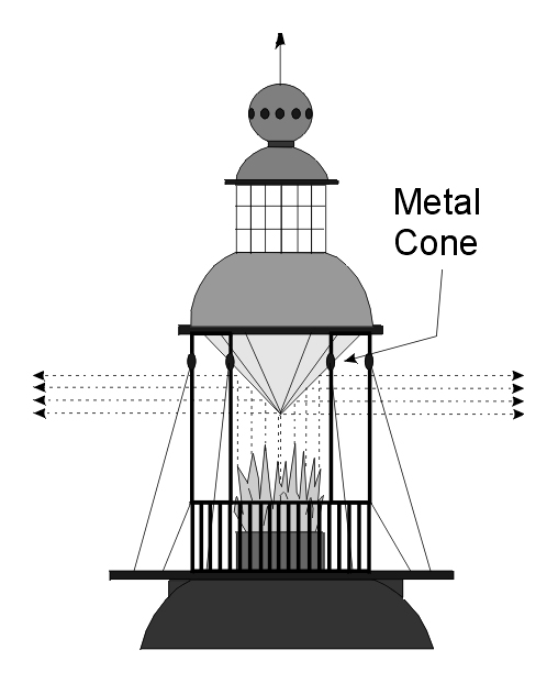
The open coal lantern room of the Cordouan Lighthouse in France with Bitry’s Cone. (1727)
In 1738, the first mention of a parabolic reflector suggests that five parabolic Braun cast-steel reflectors, each with from two to six lamps were installed at the lighthouse at Orskar, in Sweden.
Glass Facet Reflectors
The first attempt at a true parabolic reflector in England was a design by William Hutchinson in 1763. In his book 'A Treatise on Practical Seamanship' published in 1777, William Hutchinson described how his reflectors were constructed and employed:
We have had in use here at Liverpool, reflectors of 1, 2, and 3 feet focus, and 3, 5½, 7½ and 12 feet diameter, the three smallest made of tin plates soldered together, and the largest of wood, covered with plates of looking glass, fixed as near as can be to the parabolic curve, and using a copper lamp. The cistern part of the lamp stands behind the reflectors, so that nothing stands before the reflector to interrupt the blaze from acting upon it, but the tube that goes through it, with a spreading burner mouth-piece, to spread the blaze of the lamp parallel to, and with the middle of it, just in the focus or burning point of the reflector. We have a feeding can with oil to stand upon the cistern of each lamp, with a small brass cock that is turned to drop or run a little according to the consumption of oil.
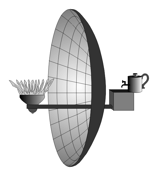
Hutchinson’s Large Glass Facet Reflector. (1763)
The Hutchinson oil lamps could be seen from ten miles away, and needed to have their flat rope wicks trimmed (snuffed) every 4 hours.
Ezekiel Walker of Lynn, England rebuilt the lighting for the Hunstanton lighthouse in 1776, and installed lamps with 18-inch parabolic reflectors made of pieces of mirror glass.
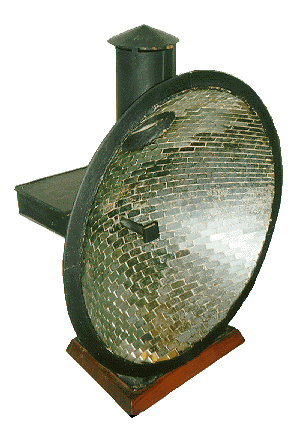
Ezekiel Walker Style Faceted Glass Reflector ca. (1776)
Ezekiel Walker used facets of mirror glass tapering in width arranged in long rows set into a parabolic plaster shell in a metal frame and fixed in position with varnish and white lead. The lamp in Walker’s reflectors used a single flat wick made of five cotton strands. Walker’s glass facet reflector’s gave about two thirds of the power of an equal diameter silvered metal reflector, and were estimated at about 1000 candlepower.
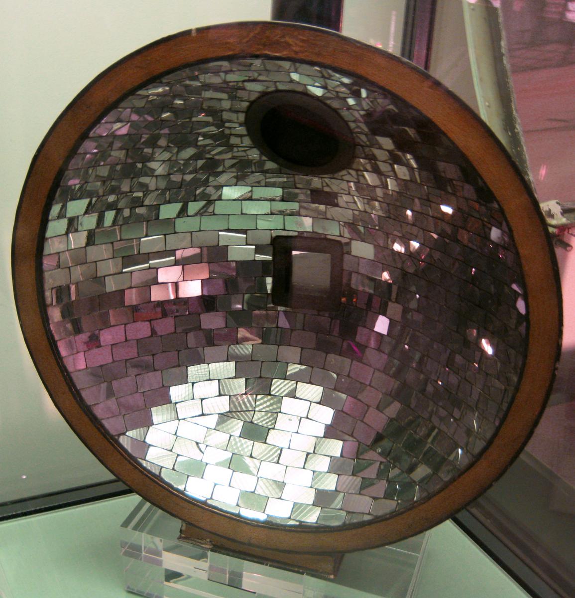
In 1777, a very unusual reflector and lamp was created and installed at the Lowestoft lighthouse in England. It was named the ‘Spangle Light’ because of its use of a concave drum on which 4000 glass mirror facets were placed. Surrounding the concave drum was a hollow tube ring with 126 holes into which short rope wicks were placed. This ring was fed from a common oil supply and when the 126 wicks were lit their light was reflected from the Spangle drum and out to the sea. The Spangle Light was first lit in 1778, but while the light was better than the previous coal fire, the 126 flames used a large quantity of oil, were difficult to maintain, and soot formed easily on the 4000 mirrors. The Spangle light was abandoned in 1796.
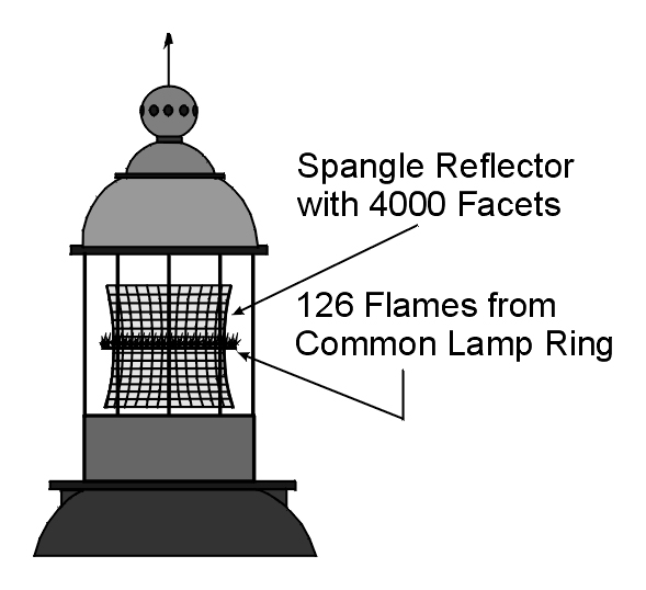
The Spangle Light used at Lowestoft Lighthouse. (1778)
Thomas Smith, Engineer of the Northern Lighthouse Board in Scotland, built a parabolic reflector made of polished tin in 1786. During the following year, Smith changed from polished tin to octagonal reflectors twelve inches in diameter made of 48 pieces of mirror glass using Ezekiel Walker’s design process. He also a made larger reflectors with 350 pieces of mirror glass set in plaster on a brass plate eighteen inches in diameter, which were used at the Kinnaird Head lighthouse in 1787. These reflectors used a lamp with four rope wicks and this reflector and lamp combination produced about 1000 candlepower. The last glass facet reflector of this type was produced in 1801 and removed from use in Scotland in 1820.
Thomas Smith’s Glass Facet Reflector ca. (1787)
Later Metallic Reflectors
During the 1770s, William Hutchinson designed a dual tin reflector with a lamp having a single reservoir and two wick tubes utilizing rough rope wicks. He suggested that a large number of such reflectors could be placed in a circle to form a fixed light. He also suggested that the reflectors could be stacked, as on a staircase, in different numbers at each lighthouse to provide a form of characteristic to distinguish one lighthouse from another. However, this suggestion would only have worked if the lights were placed more than six feet apart within the lighthouse, and the observer was within one mile of the lighthouse. Beyond one mile, the light from the various lamps would have blended in the eye of the mariner and become a single light, eliminating the ability to establish the lighthouse’s characteristic.
Hutchinson’s 11-inch Metal Reflectors used at Point Lynus, England before 1790.
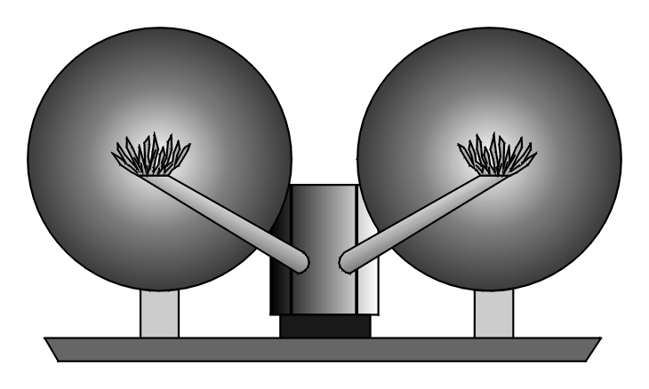
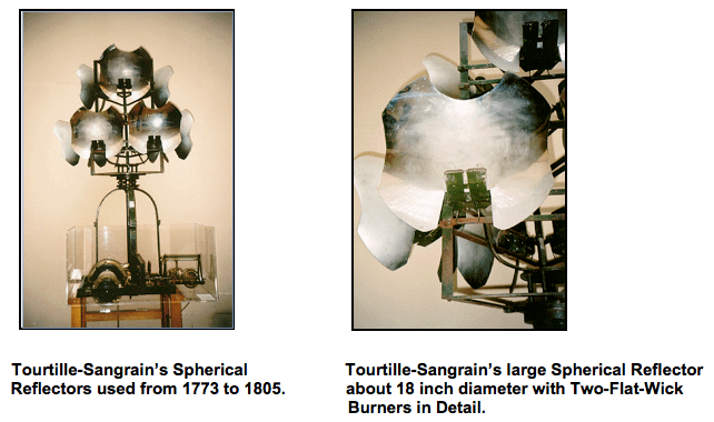
Spherical metallic reflectors designed and manufactured by Pierre Tourtille-Sangrain in 1771 were used in the French lighthouse at St. Mathieu in 1773. The spherical reflectors provided little improvement over the power of the lamp itself, and were each rated at only about 30 candlepower. In 1782, the Cordouan lighthouse in France used 80 of Tourtille-Sangrain’s smaller one-wick reflectors.
Sangrain’s small, about 6-inch diameter, One-Wick Spherical Reflector. (1782)
In 1780, the Chevalier Borda proposed a reflecting circle of spherical reflectors, which was put under test in France. Borda also designed reflector lamps mounted in several tiers on square or polygonal frames that were turned on a vertical central shaft, creating a revolving characteristic for the lighthouse. Joseph Teulere reviewed Borda’s design and proposed the use of improved parabolic reflectors and lamps in June 1783, and Ami Argand proposed the applicability of the parabolic reflector with his lamp design for use in lighthouses. In 1790, Borda had Monsieur Lenoir, a young artist of Paris, create true parabolic thirty-one-inch diameter reflectors, made of steel and clad with four leaves of silver, based on Teulere’s design, using Argand style lamps made by Antoine Quinquet without chimneys, and had him install them in the Cordouan lighthouse in France.
The first polished-metal-parabolic reflectors used in Germany were installed in the lighthouse at Memel, in what is now Lithuania, in the year 1796.
In 1803, the Inchkeith Lighthouse received Scotland’s first polished-metal-parabolic reflector. Scotland’s Northern Lighthouse Board standardized on 21-inch reflectors for fixed lights and 25-inch reflectors for revolving lights.
Bordier-Marcet’s Reflectors
In France, I. A. Bordier-Marcet, who purchased Argand’s lamp factory in France in 1801, and became successor to Argand, invented the ‘Fanal a Double Effet’ reflector in 1808, where two lamps were placed within what at first looked like a single reflector. Actually, it was a compound reflector made of two segments each with a different focus, thus allowing the two lamps to each be in the focus of a different reflector segment. This design was supposed to increase the amount of divergence produced within the compound reflector and there-by increase its output. However, the design produced only a small increase in divergence and power, while it used a far larger amount of fuel, and was soon abandoned. A 26-inch ‘Fanal a Double Effet’ reflector produced about 3800 candlepower. The word ‘fanal’ means lantern.
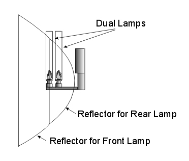
Bordier-Marcet’s ‘Fanal a Double Effet’ Reflector. (1808)
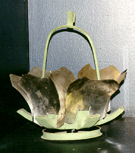
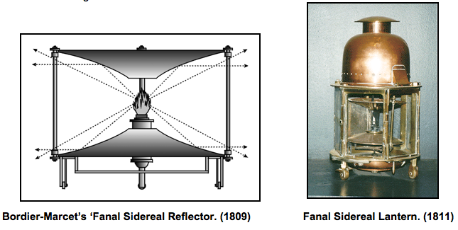
In 1809, Bordier-Marcet invented the ‘Fanal Sidereal’ reflector where two parabolic reflecting surfaces were placed one above the other. Each of the reflecting surfaces had a central hole where the lamp flame was placed. The Fanal Sidereal reflector was first used in the harbor lighthouse in Honfleur, France and the design was patented in 1812. This design allowed one lamp to give reflected light in a complete disk around the horizon although, as with all reflectors, 30 percent or more of the light was lost at the edges of the reflector, leaving light of 70 candlepower in any direction. One of the largest Fanal Sidereal reflectors, used in a lighthouse, had a diameter of 31.5 inches. The range of this design was much less than that of a standard parabolic reflector, causing Fanal Sidereal reflectors to be limited mostly to use in harbors. One of the major lighthouses to use this design was the Greifswalder Oie light in Germany, where a ‘Fanal Sidereal’ reflector was installed from 1841 to 1855. It is possible to see this design still in use today for the lighting of walkways in public places, using an electric light source. In 1860, Sir J. F. W. Herschel proposed a very similar design with the addition of a small reflector in the center near the flame that could be adjusted vertically to direct part of the light lower between the horizon and the lighthouse.
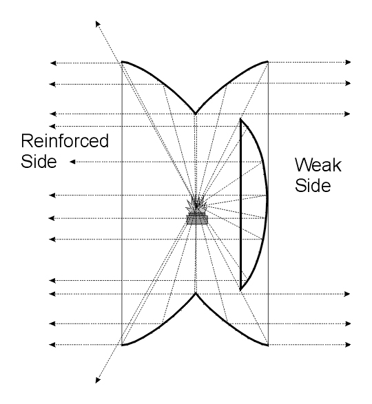
Bordier-Marcet’s ‘Fanal a Double Aspect’ Reflector. (1823)
In 1823, Bordier-Marcet created another reflector design, the ‘Fanal a Double Aspect’. In this design, the rear portion of each of two parabolic reflectors was truncated and then the two remaining portions of the reflectors were joined together facing in opposite directions. A third reflector was added behind the focus inside one of the reflector halves and facing the lamp. This reflector cut off any possible loss of light from the side it occupied (weak side) and reinforced the light projected in the opposite direction (reinforced side). Bordier-Marcet’s idea was to place these triple-reflector combinations on a common rotating chandelier with some of the reinforced reflectors facing in one direction and some facing in the opposite direction. This design would have added only a tiny amount to the light produced. The design was developed just as the Fresnel lens came into use and the ‘Fanal a Double Aspect’ was never actually used in lighthouses.
Robert Stevenson’s Reflectors
From 1803 to 1810, Robert Stevenson worked to improve the design of Scotland’s copper parabolic reflectors and lamps. He chose an improved Argand lamp and a true parabolic reflector with a heavy cladding of silver. He completed his first silver clad copper reflector in 1804 and by 1809 he had succeeded in developing a design where the lamp was able to be released from the focus of the reflector by turning a locking ring and later a locking shaft, that let the lamp assembly slide down, allowing easy wick replacement or trimming, and allowing easy polishing of the inside of the reflector. When the work was completed, the keeper raised the lamp back into its preset position, in the reflector’s focus, and locked it by turning the ring or shaft. Stevenson’s new reflectors were first installed in the Bell Rock lighthouse in 1811, and produced about 2500 candlepower.
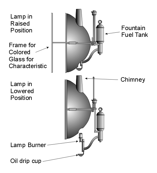
Robert Stevenson’s Retractable Lamp Reflector. (1811)
American Reflector Designs
In 1810, Winslow Lewis, a sea captain who confessed that he knew nothing about lighthouse optics, patented what he called a “magnifying and reflecting lantern” for lighthouse work. His design included a lamp, a reflector, and a magnifier.
The reflector was circular in construction and made of a thin sheet of copper formed in a generally spherical shape. It was plated with a slight film of silver with the grain and luster of tin wear, and when a finger was held near the reflector no distinct image of the finger was formed on the silvered surface. The early reflectors varied in size from 9 to 14 inches in diameter. The larger reflectors were so flimsy that when they were mounted on their wrought iron frame they were sometimes compressed significantly, altering their form and making their reflection capabilities still worse. In early models, the reflector was attached to the front of the oil reservoir and in most cases was set too far from the flame and therefore the flame was not in the focus of the reflector. A spherical reflector returns the rays of light back upon the flame and it is normal for a portion of the reflected light to be lost in passing through the flame. By accident, the Winslow Lewis design, where the flame was too far forward of the reflector focus, actually helped to allow more of the reflected light to be used. The light output of this system was very low, estimated to be less than 25 candlepower.
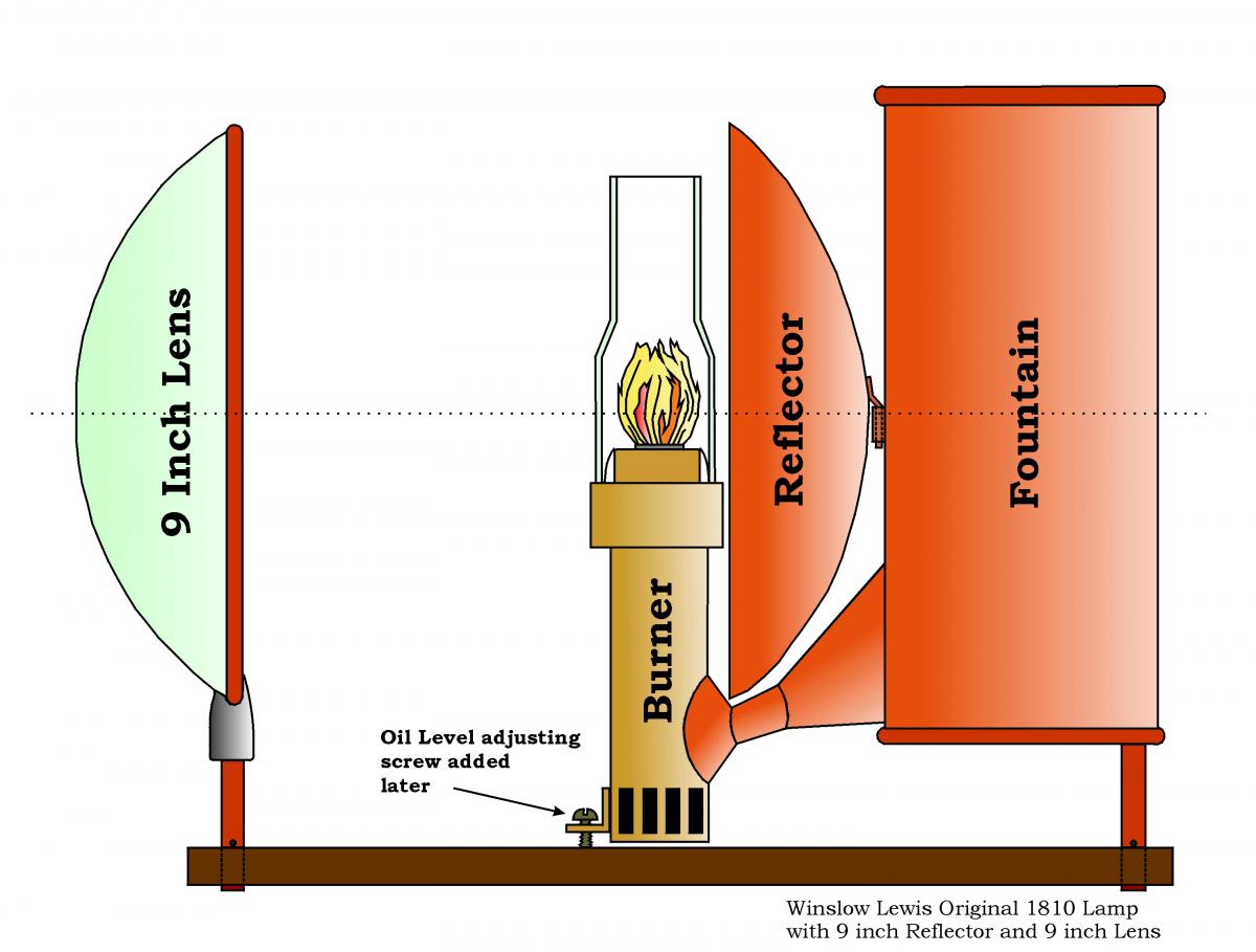
Winslow Lewis Lamp, 9 inch Reflector and 9 inch Lens, circa. 1810-1818.
Winslow Lewis also produced lamps with larger reflectors, which were mounted differently and had oil level adjusting screws on the chandelier in a mounting plate behind the lamp fountain, as shown below. An 18-inch Lewis reflector produced about 1530 candlepower.

Note: this drawing is based mostly on verbal descriptions and may not reflect the exact design.)
Winslow Lewis – Benjamin Hemmenway Lamp and Reflector in Chandelier mounting, ca. 1834-1844.
Nearly all of the American lighthouses from 1812 to 1840 used the Winslow Lewis reflector and lamp designs, and most continued to use them until about 1858. Winslow Lewis also reported that he supplied the first reflector lamps for lighthouses used in Denmark and in Nova Scotia.
Fresnel’s Reflectors
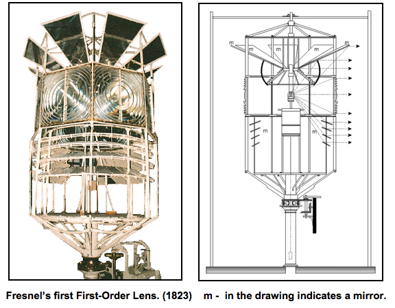
The early lens designs by Augustin Fresnel, in 1823, used flat mirrors to reflect portions of the light above and below the main dioptric belt of the lens. Later, Fresnel also used mirrors with a slight parabolic curve to improve his design.
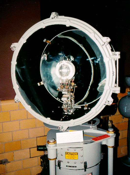
Drummond’s Lime Light with Reflector
The Drummond Lime Light is produced by two jets of gas, the one of oxygen and the other of hydrogen, ignited upon a ball of lime (Calcium Oxide) measuring only three-eighths of an inch in diameter, and placed in the focus of a parabolic reflector. Its light is equal to about 264 flames of an ordinary Argand lamp used with the best Sperm-Whale oil. It bears the name of Lieutenant Thomas Drummond, Royal Engineers, who first applied it in the focus of a parabolic reflector for geodetic purposes, and afterwards proposed it for lighthouses. So intensely brilliant was this light, that in good atmospheric conditions, observers could see their shadows at about 13 miles from the lamp. The lamp with a 21-inch reflector produced an estimated 92000 candlepower.
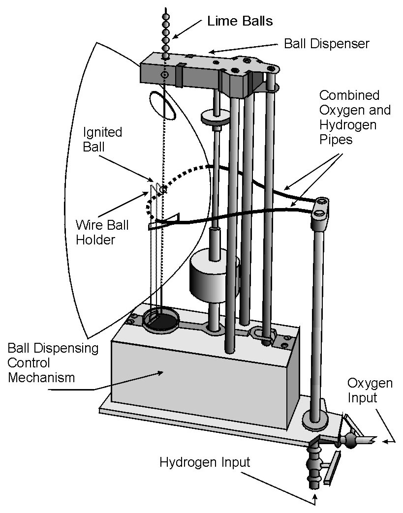
The Drummond Lime Light with Reflector.
In 1868, the American Lighthouse Board tried using the Lime light and reported on its usefulness as follows:
The Lime light required much labor, there was danger associated with the production of the gases used, it required expensive apparatus, and the liability of the lime to become deranged far outweighed any advantages in the way of superior illumination, which could be derived from it.
The Lime Light was never used in lighthouses, other than during trials, due to the great difficulty in keeping it operational for any extended period of time.
Thomas Stevenson’s Holophotal Reflector
In 1849, Thomas Stevenson invented a new reflector design, where no light escapes around the rim of the reflector, as was the case in all other reflector designs. He named his design the Holophotal Reflector, because it collected nearly one hundred percent of the available light and directed it forward in a single beam. The holophotal reflector-lens combination was first installed at the North Harbor light at Peterhead, Scotland. The Holophotal reflector is made from a spherical reflector behind the lamp, which collects all of the light rays and returns them to the lamp flame in its focus. The front portion of the reflector is a deep short focus parabolic reflector that captures the light from the lamp and sends it forward in a single beam. Inset into the parabolic reflector is a small portion of a Fresnel lens that is positioned so that it will collect all light rays that would normally escape at the edge of the reflector. This three-part reflector-lens combination collects nearly every one of the light rays and forms them into a single beam. The only light not collected is that obstructed by the lamp, chimney, lens framework, and that absorbed by the metallic reflecting surfaces. The Holophotal design uses both a reflector and a lens and it is known as a Catadioptric or reflective / refractive illuminator.
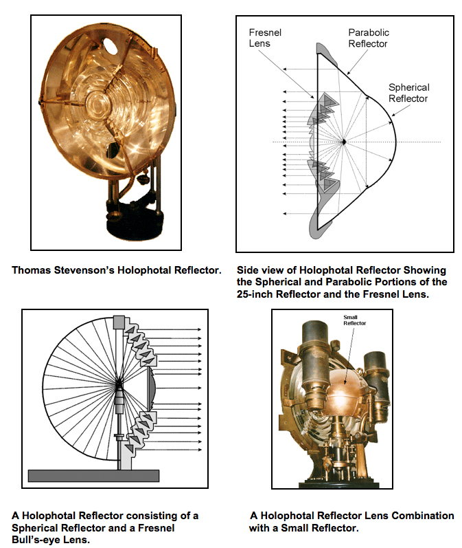
Both Thomas and Alan Stevenson proposed various modifications to the holophotal reflector and in the 1850s a spherical reflector was mated to a Fresnel bull’s-eye lens. This combination collected nearly all of the available light and was used in harbor and range lights. It was eventually replaced by the lens with spherical doubly reflecting prisms, which will be discussed in the section on Glass Doubly Reflecting Prism Designs.
Lighthouse Board improved reflector design using a one-inch burner with a rack and pinion wick adjustment.
After the American Lighthouse Board took over in 1852, their reflector design was further improved with a one-inch rack and pinion burner and rod heater, and by using still more accurate parabolic reflectors. The mounting to the chandelier was also improved. One thumbscrew was used to firmly attach both the lamp and the reflector to the chandelier. This design was used by the Lighthouse Board beginning about 1860 for channel, range and beacon lights, and continued to be used into the early 1900s.
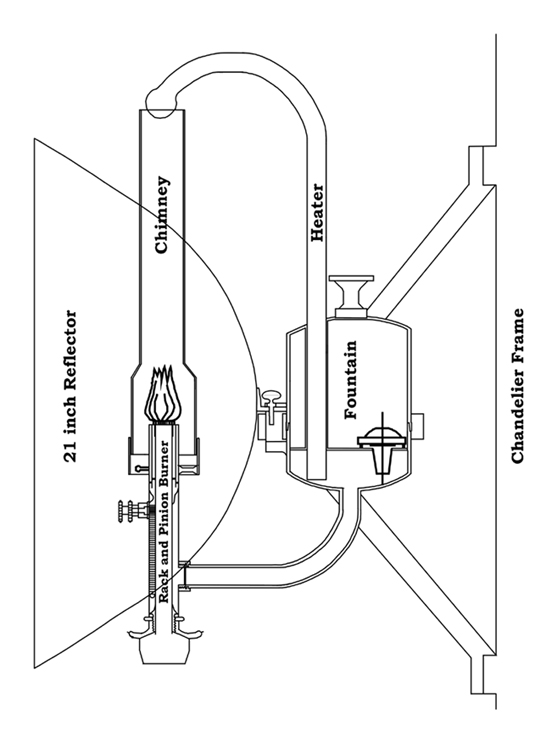
Winslow Lewis – Benjamin Hemmenway, style Argand Fountain Lamp and 21 inch reflector showing Chandelier mounting with lamp as modified by the Lighthouse Board. (1860)
Osnaghi’s Reflector
In 1873, Professor Ferdinand Osnaghi of Vienna, Austria developed an improved Holophotal reflector much like the design of Thomas Stevenson.
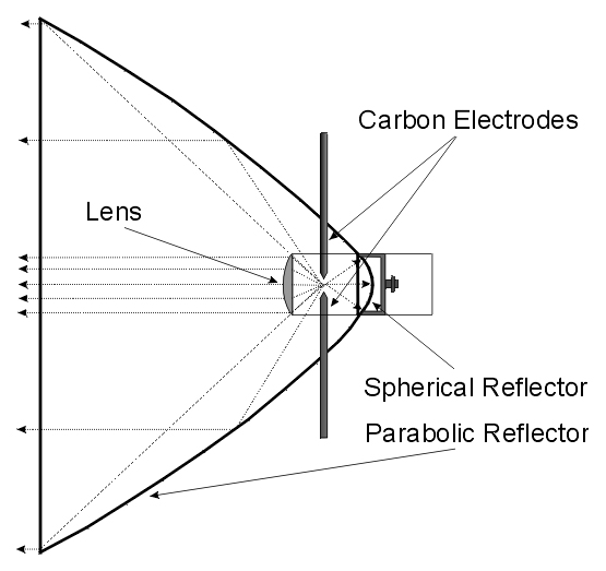
Osnaghi’s Parabolic Reflector for Intermittent Lights. (1873)
Osnaghi’s design was called the ‘Parabolic Reflector for Intermittent Lights,’ and was specifically designed for use with the electric-arc lamp. It was made from polished silver clad copper and was formed with a very small 3.3-inch spherical reflector attached at the back of a deep 15-inch parabolic reflector. It also had a 3.3-inch plano-convex lens to concentrate the light. It was found that the electric-arc lamp worked better within a Fresnel lens or with a glass-parabolic mirror and Osnaghi’s reflectors were seldom used.
German Metal Range Light Reflectors
Germany produced mirrors formed of metal to a parabolic curve in the vertical dimension and to a hyperbolic curve in the horizontal direction in the late 1800s.
A Parabolic – Hyperbolic metal Mirror used in German range lights in the late 1800s.
Lightship Reflectors
Lightship reflectors came into use in Scotland in 1807 using a design by Robert Stevenson. Reflectors remained the main form of lightship illumination for many years. In 1845, Alexander Gordon proposed the use of a wrought iron tower on lightships to house the reflectors and lantern, however, lightships of the day were made of wood, and this style of tower did not come into use until lightships were made of iron. Reflectors were eventually replaced by Fresnel lenses mounted on gimbals after about 1873.
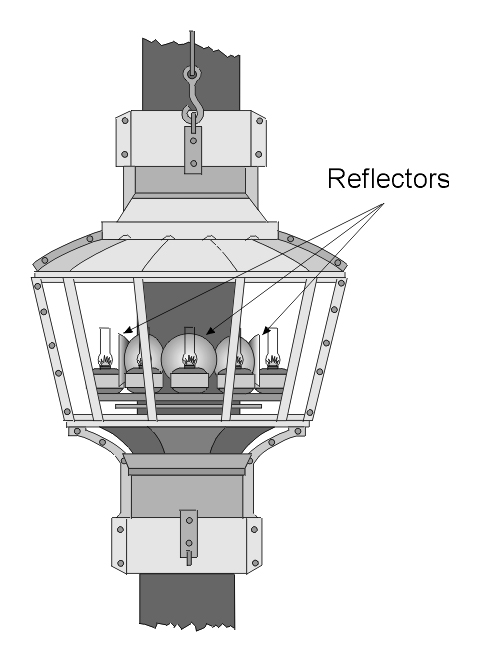
Robert Stevenson’s Lightship Lantern with Reflector Lamps. (1807)
The reflectors used on lightships were arraigned in a way that the beam of light from one reflector just overlapped the beam from the reflectors adjacent to it on either side. This supplied a nearly continuous horizontal band of light similar to that of a fixed lens. The problem of the ship’s motion was overcome by hanging each of the lamps and reflectors on its own set of gimbals, which counteracted the ships motion.
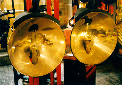
Lightship Reflectors. Note the gimbal brackets above and behind each reflector.
Glass Reflectors and the Mangin Mirror
In addition to the standard metallic parabolic reflectors, other types of light reflectors were developed. In 1788, Thomas Rogers proposed several reflectors of blown glass that were silvered on the back. These reflectors proved too fragile to be used for any length of time and were soon abandoned. Another design was developed by Major Fitzmaurice, in England, using reflectors made of porcelain with the interior having a glaze of platinum. The reflectors cost about one fourth that of silvered metal, but the interior surface was wavy and not very bright. Porcelain reflectors were used at the Sunderland Lighthouse, in England, in 1860.
Professor Justus von Liebig first proposed making parabolic reflectors out of glass in 1856, but he was not able to develop a way to manufacturer them. Later, in 1859, he also invented a way to coat the back of a blown or pressed glass reflector with pure silver. This coating method increased its reflective properties and allowed 91percent of the light to be reflected vs. 55 percent for silvered metal reflectors. Glass reflectors were more fragile than metallic reflectors, but their improved reflecting properties as well as their ease of maintenance made them desirable in lighthouse applications.
Glass Doubly Reflecting Prism Designs
Another form of a Catadioptric (reflecting / refracting) reflector design was constructed in 1849 by Thomas Stevenson in Scotland. He developed a reflector using only doubly reflecting glass prisms placed in such a manner that they reflected nearly all light entering the prism from its longer side. In the diagram below, light from the focus of the lamp (point F) enters the longer and slightly curved side of the doubly reflecting prism, is reflected from surface (A) to surface (B) and is returned to the focus of the lamp (point F). Due to the properties of the glass and the prism design, over 80 percent of the light is returned with just a loss for its passage through the glass.
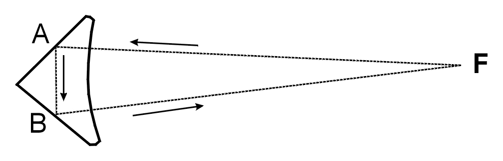
Doubly Reflecting Prism Operation.
There were two styles of doubly reflecting prism panels designed by Thomas Stevenson and manufactured by James Chance, in England. The flat or semi curved panel is shown below and is the most commonly used. It was designed and manufactured by James Chance in 1862 and first used in 1863 at Cape Saunders, New Zealand. In this design, doubly reflecting prisms are generated around a vertical axis yielding glass curved in the horizontal direction only and are placed behind the lamp in the rear portion of a Fresnel lens where they reflect the light forward that would normally be wasted on the land side of a fixed lens. This form was difficult to design, although it was found easier to produce using crown glass, and therefore was less costly. This design was also used to increase the power of some flashing lenses.
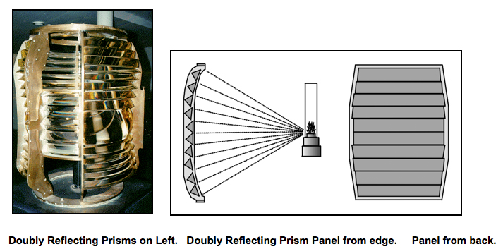
The second form of doubly reflecting prism panel is the spherical prism mirror where the prisms are generated around a horizontal axis forming nested rings that create a hemispherical bowl design behind the lamp. The first spherical prism mirror was proposed in 1850 by Thomas Stevenson and was partially constructed by Professor John Adie in 1852. This design initially required the use of flint glass, and it was costly, and very difficult to manufacture. Later, when manufacturing techniques were improved, it could be more easily produced, however, only a few spherical mirrors of this style were made and used mostly in harbor range lights.
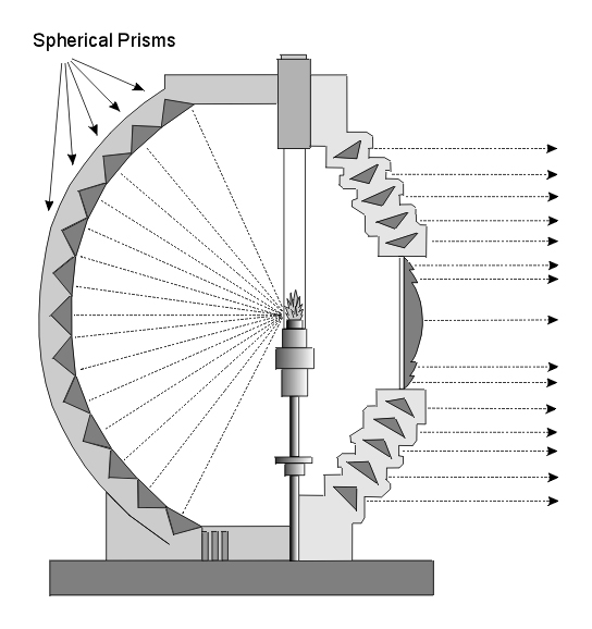
Lens with Spherical Doubly Reflecting Prisms.
The Mangin Mirror
In 1867, Sautter Lemonnier and Co., a French lighthouse equipment manufacturer, developed the first spherical mirror specifically for use with the electric arc lamp. Their design was significantly improved in 1874 when Alphonse Mangin, a Colonel in the French Army, designed a new form of glass-spherical mirror where the reflecting material was deposited on the rear, or second surface, of a glass lens. The front, or first surface, of this lens was ground to magnify the reflected light and to correct the spherical aberration of the second surface, producing the effect of a parabolic mirror. This lens-mirror hybrid is called a Mangin Mirror. After 1876, Sautter Lemonnier and Co. became one of the major producers of Mangin Mirrors for use in searchlights and in lighthouses.
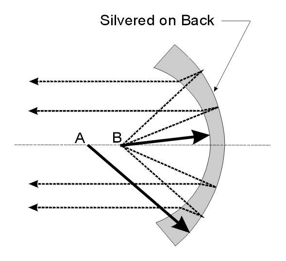
Design and Operation of a Mangin Mirror. (1874)
The Mangin Mirror is created by forming a glass lens with the curvature of the inside radius (point B) different, smaller, than the radius of the outside or back of the lens, (point A). The lens is then made into a mirror by silvering the back surface. Point B, serves as the focus of the Mangin Mirror. The rear surface reflects the light and the front surface refracts or bends the light. Mangin mirrors were used mostly in conjunction with electric-arc lamps.
Glass Split Mirror Designs
Beginning in late 1909, Raymond Haskell, Assistant Superintendent of the Third District Depot, began developing the spherical-glass mirror reflector-lens combination. In this design, a Fresnel lens was modified with a prism panel removed and replaced with a spherical mirror designed to reflect the light back upon the flame in the focus of the lens and then out through the lens prism panel opposite the mirror. With gas and acetylene lamps, this created a brighter flame area and increased the light output. However, this combination was not efficient for kerosene and Incandescent Oil Vapor (I.O.V.) lamps, because most of the reflected light was lost when it returned and was blocked by the nearly opaque mantle and by the large burners.
This problem was resolved by the creation of the split-mirror reflector. This design split the spherical-glass reflector described above vertically into two half mirrors. Each half was then turned slightly, focusing the light about one inch outward from the original position. Thus the left half of the split mirror would focus to the left of center and the right half would focus to the right. The result of this split mirror design brought the reflected light back toward the flame, but beside the mantle and burner, thus increasing the light. If you stood in front of the lens you would observe the flame and two additional reflected light sources spaced closely together. Later, the mirrors were also split horizontally at the center and mounted with adjustment screws that could be used to fine tune the focus of the mirror panels (see detail view below).
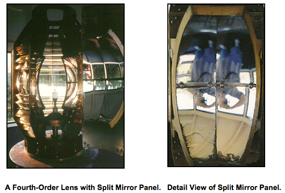
In the larger order lenses, two small mirrors performing the split mirror function were placed on either side of a large mirror shaped parabolicly in the vertical dimension only and flat in the horizontal direction. This three-split mirror combination replaced the doubly reflecting prisms previously discussed in lenses where the otherwise useless light on the landside of the lens could be collected.
Glass Searchlight Designs
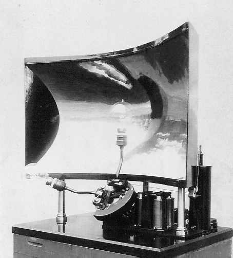
In Germany in 1885, Johann Schuckert invented a machine that could accurately grind glass into a parabolic or Mangin curve. The Heligoland lighthouse in Germany used four searchlights made using Schuckert’s process and constructed by Siemens in 1902. Three searchlights were set at 120-degree angles on a rotating platform in the lower portion producing a flash of 1/10 second followed by 5 seconds of darkness. There was one additional searchlight mounted above rotating 3 times faster than the other searchlights. The upper searchlight was discontinued after World War II, and used only as an emergency backup. Each searchlight used a glass-parabolic reflector with a diameter of 755 mm. (29.7 inches), and each searchlight produced an average of 40 million candlepower. Schuckert’s company was merged into the Siemens Company in 1903. In Germany this lighthouse was known as the ‘Schnellblitzfeuer’ or very quick flashing light. Searchlight designs were also used in America at the Southwest Ledge light as early as 1900.
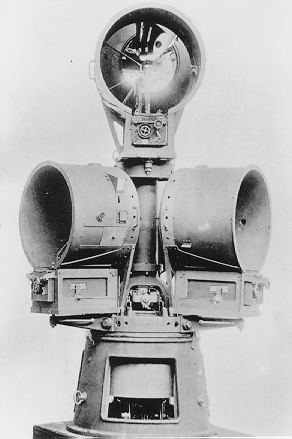
The Illumination Optics of the Heligoland Lighthouse in Germany.
This same general design evolved into the U.S. Coast Guard DCB-24 and DCB-224 rotating searchlights that are used in many American lighthouses today.
DCB-24 Searchlight with 24-inch Glass-Parabolic Reflector.
Glass Parabolic Mirror Designs
In 1903, a flat parabolic cylinder mirror, parabolic only in the vertical dimension and covering just 180 degrees of the horizon, was installed in the Travemünde lighthouse in Germany.
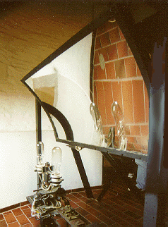
The Parabolic Cylinder Mirror in the Travemünde Lighthouse, Germany. (1903)
An alternative to the Fresnel lens system and searchlight designs was the use of large parabolic mirror panels of silvered glass arranged around a common light source. This idea was developed by Charles Stevenson in 1930, and was often used in Scotland, England and elsewhere due to its low cost as compared to a Fresnel lens. However, the effective light collection of this mirror system is little more than half that of a lens system and stray light coming from the sides of the beams could be a problem in some installations. These mirrors were not used in America.
Light Bulb Reflectors
The early 1900s saw the development of metallic and glass reflector designs for use behind and as a part of light bulbs. The power of light bulbs could be enhanced by placing a reflector behind the bulb alone or within a lens.

Sealed-beam Lamps with Integrated Parabolic Reflectors
The use of reflectors behind light bulbs soon gave way to the Sealed-beam lamp bulb where a glass-parabolic reflector is built into the light bulb itself. Sealed-beam lamp bulbs became available in the early 1900s as the automobile became popular. A U.S. Coast Guard study in June 1954 found: “Ninety manned lighthouses in the First Coast District were examined. Only fourteen of these 90 lighthouses gave as much beam candlepower as one automotive headlight.”
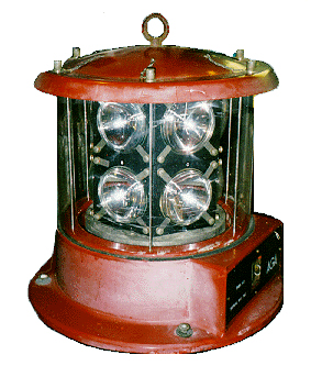
An English emergency flashing unit using Sealed-beam lamps.
While Sealed-beam lamps were more powerful, they were infrequently used in America, although they became quite popular in the rest of the world. In addition to the Sealed-beam lamps a number of the other modern light bulbs containing integrated parabolic reflectors such as the Osram lamp bulb came into use throughout the world’s lighthouses beginning in the 1960s.
As you have seen, reflectors came in many styles, shapes and materials. Reflectors were nearly abandoned when Fresnel lenses were first made available, and yet they later returned to a prominent position in forming ‘The Mirror of Light’ for lighthouses.